|
|

Rank: Advanced Member
Groups: Member
Joined: 10/2/2007
Posts: 5,967
|
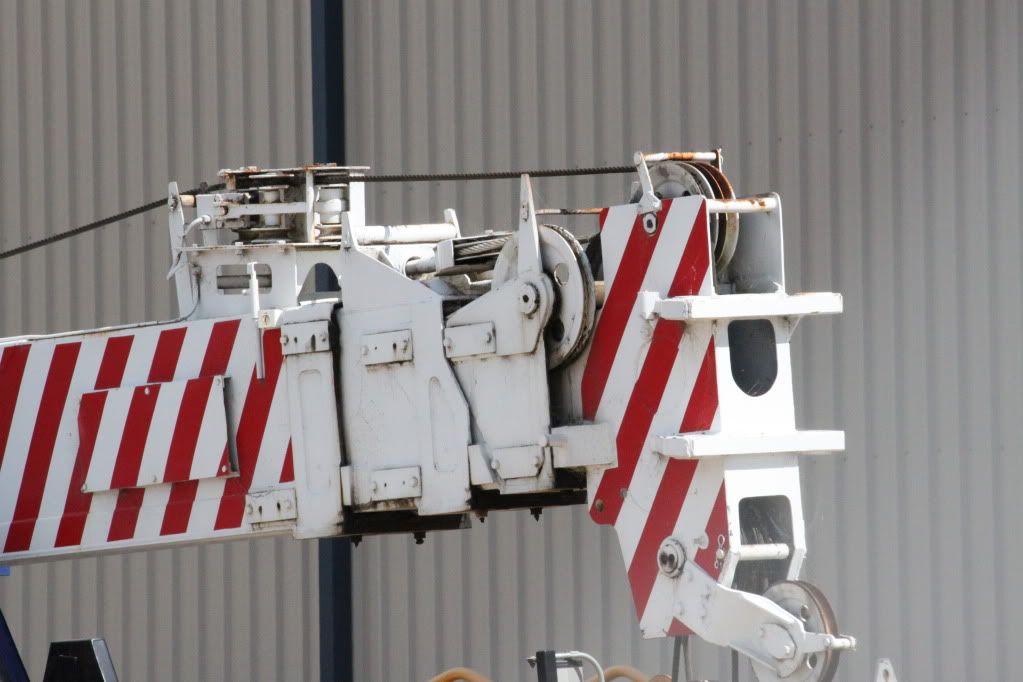
yes, now that i think of it.... its not a pin system.... its a Terex and on tele 2 there is a chain on the underside of the boom, im assuming that would be said pulley system?
|
|

Rank: Advanced Member
Groups: Member
Joined: 4/11/2008
Posts: 1,605
Location: North Wales
|
DeWoc19 wrote:im assuming that would be said pulley system? Sounds like it mate, what RT is it you know? Gaz
|
|

Rank: Advanced Member
Groups: Member
Joined: 10/2/2007
Posts: 5,967
|
not quite sure, i can find out tomorrow
|
|

Rank: Advanced Member
Groups: Member
, Moderator
Joined: 1/15/2007
Posts: 4,089
|
What a GREAT thread!!! I mean we are seeing some awesome pictures, in the yard in the field from the operators seat. An education on how the booms of various operating systems work. Thanks for all the contributions and a special tip of the hat to Gaz for the thread. Gaz-special cookies for you!!!
Bob Bobs CranesCome Over To The Lift Side . . . . . . . We Have Cookies!!!!
|
|

Rank: Advanced Member
Groups: Member
Joined: 4/11/2008
Posts: 1,605
Location: North Wales
|
This is a good example, Grove use a twinlock pin system....there are 2 pins either side of the boom, look at the side of the GMK7550, just before the Amquip sign there is a square hole, this is the half way boom point, on a 7550 i think it is 45%, then look further up you can see 2 more square holes, this is 90% & 100%. The hole at the bottem is where it would be pinned when retracted. It's harder to spot the Liebherr and demag ones because they are on the back of the boom. Thanks for the cookies Bob my man, i was starving! lol Gaz
|
|

Rank: Advanced Member
Groups: Member
Joined: 10/2/2007
Posts: 5,967
|
so is the twinlock a better or strong system than a single pinning system? in theory you would think 2 would be better than 1, is that the case here?
|
|

Rank: Advanced Member
Groups: Member
Joined: 4/11/2008
Posts: 1,605
Location: North Wales
|
DeWoc19 wrote:so is the twinlock a better or strong system than a single pinning system? in theory you would think 2 would be better than 1, is that the case here? That would really depend on the engineering, if the 1 pin on the back of the boom was twice the size of the 2 on the side then who's to say. The reason the back of the boom is used is because of deflection as the boom bends the forces through the boom 'push' the pin into the hole, there is no sideways force on it. When there on the side they will suffer forces that a pin on the back do not. That however is not to say that those pins cannot take that pressure! It's 2 different systems that both work. Gaz
|
|

Rank: Advanced Member
Groups: Member
Joined: 4/11/2008
Posts: 1,605
Location: North Wales
|
I've eventually found a picture that clearly shows the set pin holes on a Liebherr, this is a LTM1500, tele 1,2 and 3 are out 92%, 4,5 and 6 are retracted. The reason the 3 lower section are used is they are stronger, because the luffer is on, the tower (main boom) will remain in a upright postion the most it can, usually between 75 and 82 degree. This means the weight of the boom does not effect the tipping balance of the crane, it is kept near vertical so the stronger sections are used. You can clearly see where the pins for the 100, 92 and 46% set lengths are.  Now to bake your noodle some more, on this job we needed a extra 2t of capacity to get 2 tower sections (we we're removing a tower crane), to do this we tele the boom back in and reset the configuration, tele 1 is still at 92, but 2 & 3 are now at 46, this shortened the boom by over 14m but because the tower is stronger we gained our 2t on capacity while still clearing the building.  Those of you who have a YCC LTM1800, look at your main boom, there are little recesses for the spring clips to hold the boom out, 1 at 46%, 1 at 92% and 1 at 100%....would you look at that! Gaz
|
|

Rank: Advanced Member
Groups: Member
Joined: 9/22/2007
Posts: 5,860
Location: Louisville
|
this is very interesting! thanks for the info Gaz, i never really paid attention to the holes in the 550. 
Brandon my youtube channelMy Facebook Page
|
|

Rank: Advanced Member
Groups: Member
Joined: 6/23/2010
Posts: 1,734
Location: Hunter Valley
|
We have an old 20t P&H as our yard crane and its an example of a pulley system. Would i be right? 
|
|

Rank: Advanced Member
Groups: Member
Joined: 1/11/2007
Posts: 9,079
Location: Lincolnshire
|
Gaz wrote:I've eventually found a picture that clearly shows the set pin holes on a Liebherr, this is a LTM1500, tele 1,2 and 3 are out 92%, 4,5 and 6 are retracted. The reason the 3 lower section are used is they are stronger, because the luffer is on, the tower (main boom) will remain in a upright postion the most it can, usually between 75 and 82 degree. This means the weight of the boom does not effect the tipping balance of the crane, it is kept near vertical so the stronger sections are used. You can clearly see where the pins for the 100, 92 and 46% set lengths are. http://i283.photobucket.com/albums/kk309/dhgareth/DSC_0335.jpgNow to bake your noodle some more, on this job we needed a extra 2t of capacity to get 2 tower sections (we we're removing a tower crane), to do this we tele the boom back in and reset the configuration, tele 1 is still at 92, but 2 & 3 are now at 46, this shortened the boom by over 14m but because the tower is stronger we gained our 2t on capacity while still clearing the building. http://i283.photobucket.com/albums/kk309/dhgareth/IMG_0776.jpgThose of you who have a YCC LTM1800, look at your main boom, there are little recesses for the spring clips to hold the boom out, 1 at 46%, 1 at 92% and 1 at 100%....would you look at that!
Gaz This is when I first realised the concept of pinning booms and actually thought YCC came up with a good way of doing it on a model. But it was the internal mechanism's that I did not understand. I think the only caveat to all Liebherrs using 0%, 46%, 92 % and 100% is the 112. If I am thinking correctly, this does 0%, 50% and 100%? Not sure if this was already mentioned and I missed it, so apologies if it has. Thanks a lot for all the info Gaz. This really has been an insight and education. If I lived a bit closer I'd personally bring you a plate of warm cookies and milk  Might be frozen by the time I make it to London though!! Paul R
|
|

Rank: Advanced Member
Groups: Member
Joined: 4/11/2008
Posts: 1,605
Location: North Wales
|
Robert Heuston wrote:We have an old 20t P&H as our yard crane and its an example of a pulley system.
Would i be right? You got it mate. Paul, look at your model 112 (or 1 of them  ), look at the back of the base section of the boom and see what is cast in the detail and then tell me the percentage each section can be pinned at. Gaz
|
|

Rank: Advanced Member
Groups: Member
Joined: 1/11/2007
Posts: 9,079
Location: Lincolnshire
|
Gaz wrote:Paul, look at your model 112 (or 1 of them  ), look at the back of the base section of the boom and see what is cast in the detail and then tell me the percentage each section can be pinned at. Gaz To be honest, I am not sure. There are only 2 positions for it to be pinned, but whether this is 50 and 100 or 46 and 92, or 50 and 92 I don't know. But certainly there is not 3. But on a completely different note, you have reminded me that I have to paint some black on the FB 112's TY to match the 1:1 version  Paul R
|
|

Rank: Advanced Member
Groups: Member
Joined: 4/11/2008
Posts: 1,605
Location: North Wales
|
There the two mate, the retracted position hole appears to be hidden by other detail but there is 1 50% and 1 100%, until I researched this last night i never knew, i assumed it ran the same as all other Liebherr pinned systems but it does not. The must be a reason for it, most likely due to the size of the boom there is very little strength difference between 92 and 100% so the just have the 1.
Gaz
|
|

Rank: Advanced Member
Groups: Member
Joined: 10/2/2007
Posts: 5,967
|
man this is a good learning lesson, thanks Gaz..... really learned something new today and your pictures have helped to understand even better!
|
|

Rank: Advanced Member
Groups: Member
Joined: 4/11/2008
Posts: 1,605
Location: North Wales
|
DeWoc19 wrote:man this is a good learning lesson, thanks Gaz..... really learned something new today and your pictures have helped to understand even better! You welcome my man, you think about it I do this every day of my working life, I don't even think about it any more, its all on the computer in front off me. When you do the course to drive these cranes at Liebherr's you have to know the pinning system inside out so if the computer screen goes down and you have to bring the boom in you have to do it by the feel of the machine, listen for the sounds of the pins going in and use the switches to release and engage them in the right order, so naturally I know how it works. Gaz
|
|

Rank: Advanced Member
Groups: Member
Joined: 6/23/2010
Posts: 1,734
Location: Hunter Valley
|
I'm being sent do do my C6(60t) ticket next year for work, the place they are sending me to has a 23t p&h which has the pulley system, so when I hop into a pinned system I'll basicly need to be trained all over again, right?
|
|

Rank: Advanced Member
Groups: Member
Joined: 4/11/2008
Posts: 1,605
Location: North Wales
|
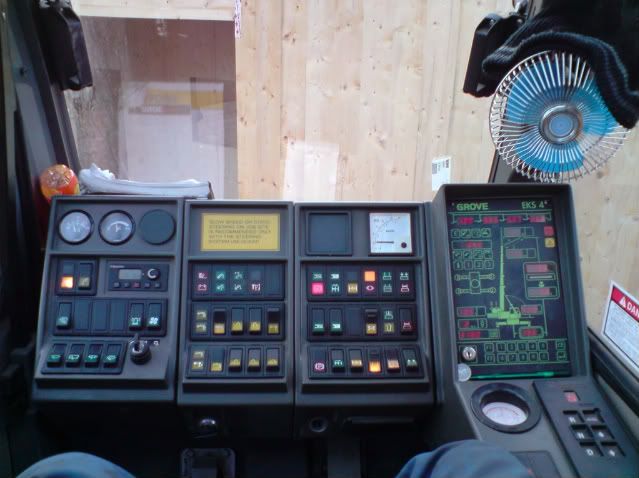
Robert Heuston wrote:I'm being sent do do my C6(60t) ticket next year for work, the place they are sending me to has a 23t p&h which has the pulley system, so when I hop into a pinned system I'll basicly need to be trained all over again, right? Trained to use that pinned system, machines are different, the liccon system that leibherr use is completely different to say, the EKS 4 system of the older Groves that i used to drive. I'm not sure how it works in Oz Bob but in the UK once you get your mobile crane license you can drive any mobile....however you have to be trained on each machine you use by your employer, this can take a day on say a little 30tonner or 3 - 4 weeks on the big stuff. So its not just pinned booms and pullys that change as the machine does....the whole operating system does, you will be trained on how the whole machine works, not just the boom. This is a old GMK3050 i used to drive, It was a 2 stage pully system, tele 2 3 and 4 went out on 1 tele ram but there was a second in there that sent out tele section 1. Tele 1 was only used for height and heavy lifting close radius.....the section was 2 heavy for radius work. Look how much different the old Grove is to my current Liebherr.  Gaz
|
|

Rank: Advanced Member
Groups: Member
Joined: 12/23/2008
Posts: 390
Location: Burnie, Tasmania, Australia
|
Wow, an education and learning of a crane operation. Many thanks Gaz. Learn something new everyday.
Now i know why many of the older Kato and Tadano cranes have the pulley system like the P&H pic above.
As Mammoet says "SIZE DOES MATTER". Slowly collecting Mammoet 1:50 scale stuff. Mainly cranes!
|
|

Rank: Advanced Member
Groups: Member
Joined: 10/30/2006
Posts: 889
Location: Las Cruces, NM
|
Thanks for all of this great information! This is truly a highly educational thread. Now I want to go and bore out some holes on my models so they can telescope to realistic configurations! Dan
1:1 or 1:50, I am still in awe. 
|
|
|
Guest |
